
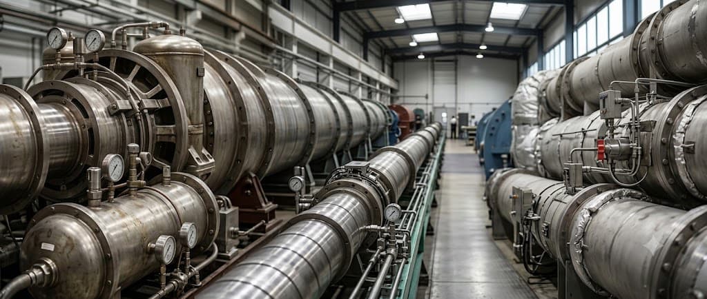
Trisonic Wind Tunnel
Trisonic Wind Tunnel
A blowdown wind tunnel that reproduces subsonic, transonic and supersonic flow in a single facility.
Real-time control of the variable nozzle changes the Mach number continuously while key aerodynamic data such as pressure, force and vibration are acquired.
Specifications
- Type
- Blowdown
- Test Mach number
- M 0.5 – 3+
- Test section
- 500 × 500 mm
- Test time
- ~ 60 s
- Angle of attack
- −10° ~ +15°
- Stagnation pressure
- 1 ~ 9.8 atm
- Mass flow rate
- 60 ~ 200 kg/s
Key Features
01
Three speed regimes
- Subsonic (M < 1)
- Transonic (0.8 ≤ M ≤ 1.2)
- Supersonic (1.2 < M < 5)
02
Continuously variable Mach number
- Real-time variable nozzle control for continuous Mach variation
- Model attitude control from −10° to +15° angle of attack
03
Key aerodynamic data
- Acquisition of pressure, force and vibration data
- Reliable operation in high-pressure, high-speed flow
System Layout
Loading 3D model
Components

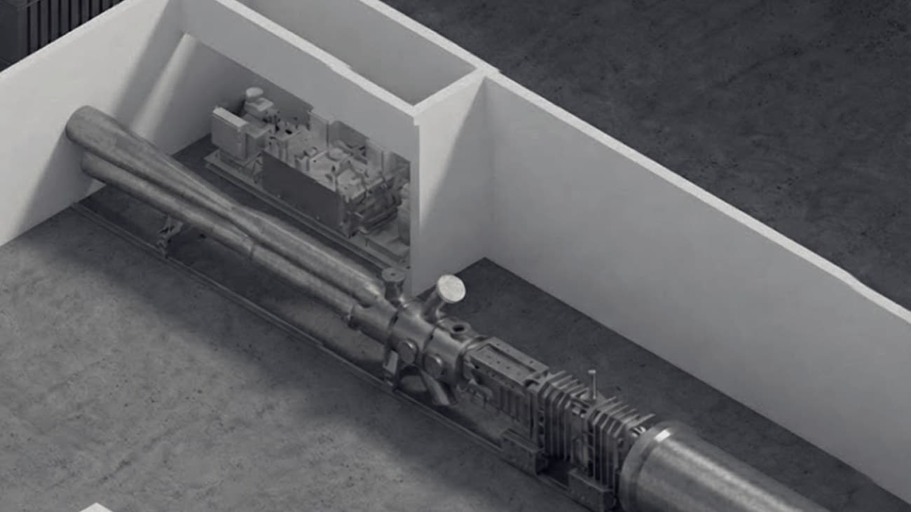
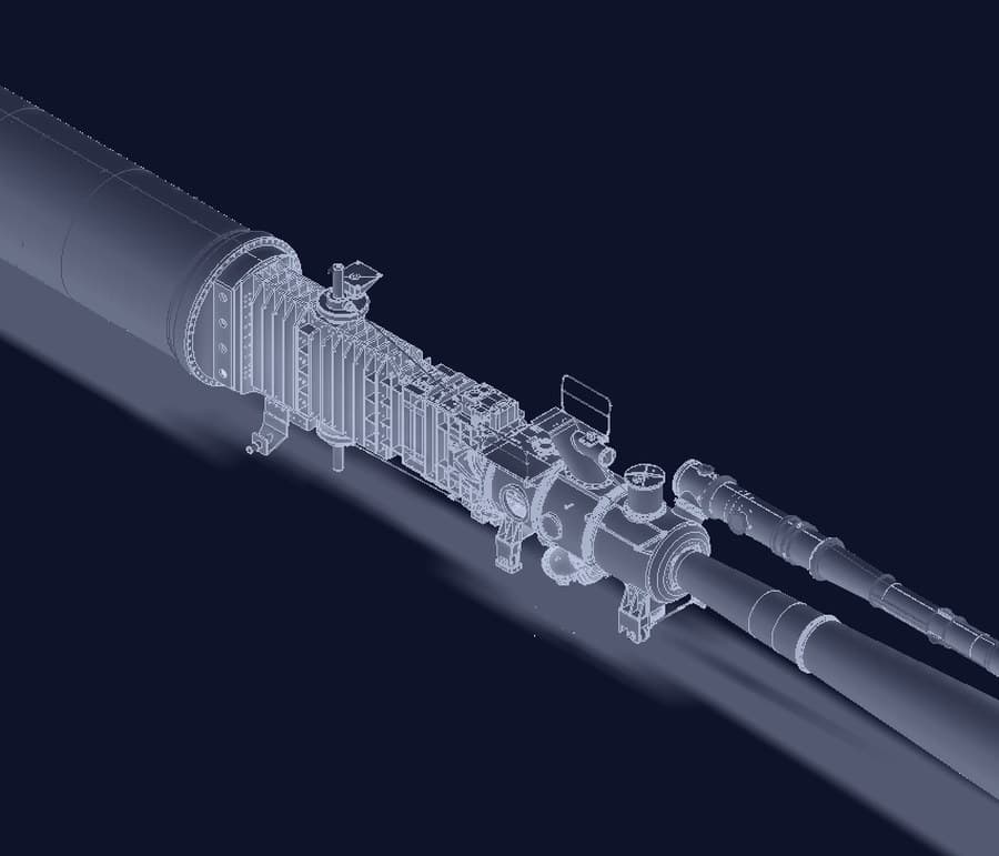
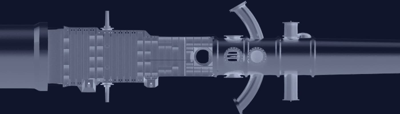
Based on the TVM-500 trisonic wind tunnelTotal lengthapprox. 27,450 mm
Piping Diagram
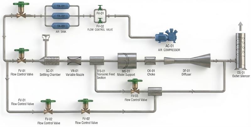
High-flow Supply and Control System
High-Mass-Flow Supply & Control
Supplies and regulates 60 ~ 200 kg/s of air.
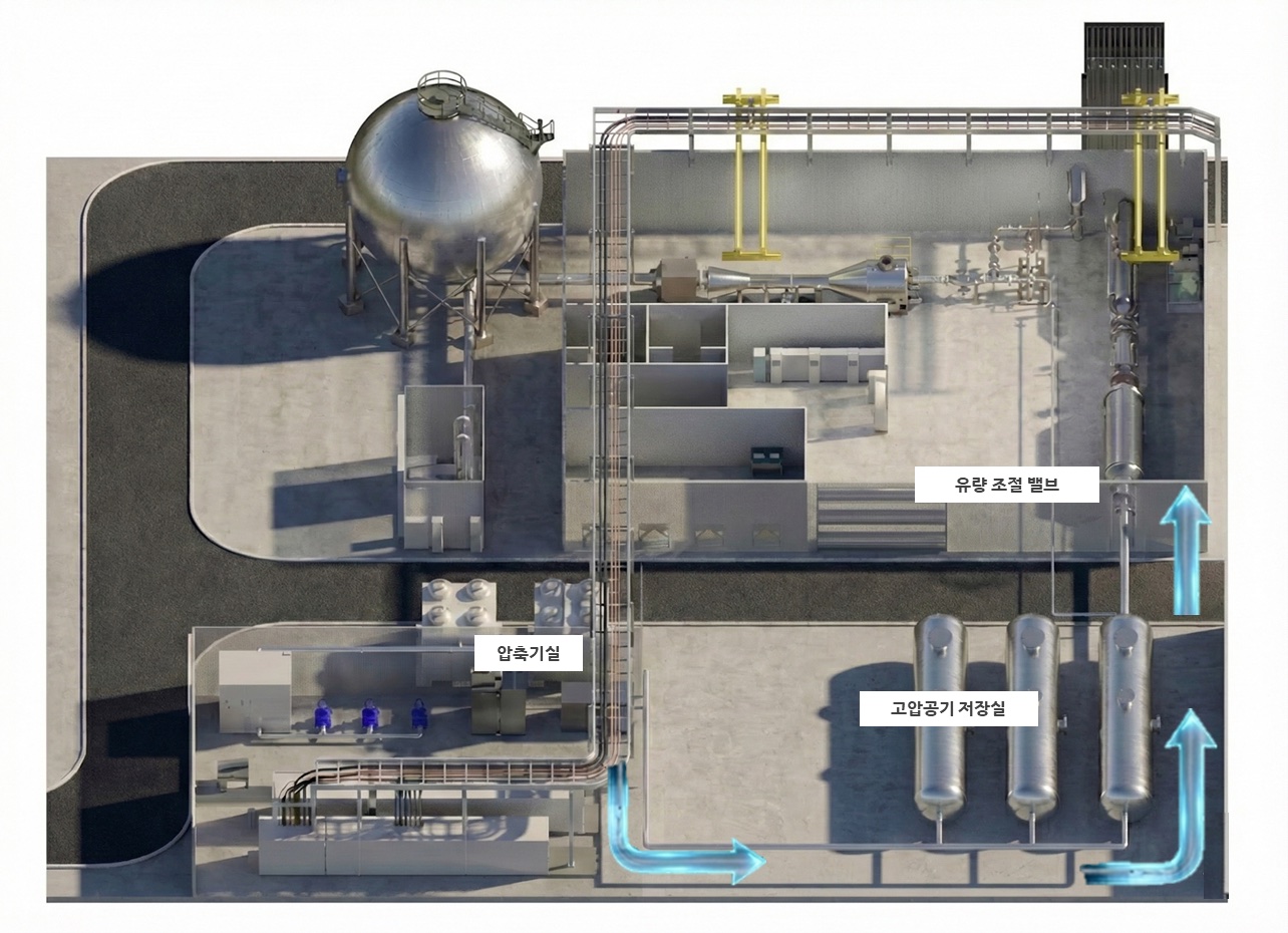
High-pressure air from the compressor room is stored in the air storage room, passes the flow control valve into the settling chamber, and is conditioned there before entering the variable nozzle.
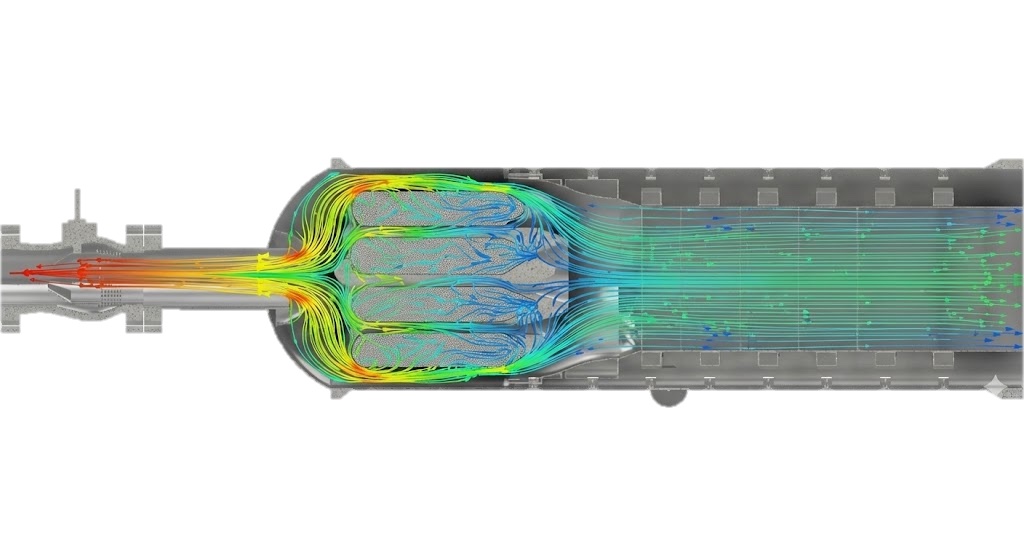
Settling chamber flow conditioning
01
Flow control valve
- Flow control / condition setting
02
Settling chamber diffusion
- Flow deceleration and initial stabilization
03
Silencer
- Suppression of high-speed jet noise
04
Screen 1
- Easing non-uniform flow
05
Honeycomb
- Removing swirl and vortices
06
Screen 2
- Improving velocity and pressure uniformity
07
Screen 3
- Reducing fine-scale turbulence
08
Into the variable nozzle
Control Points
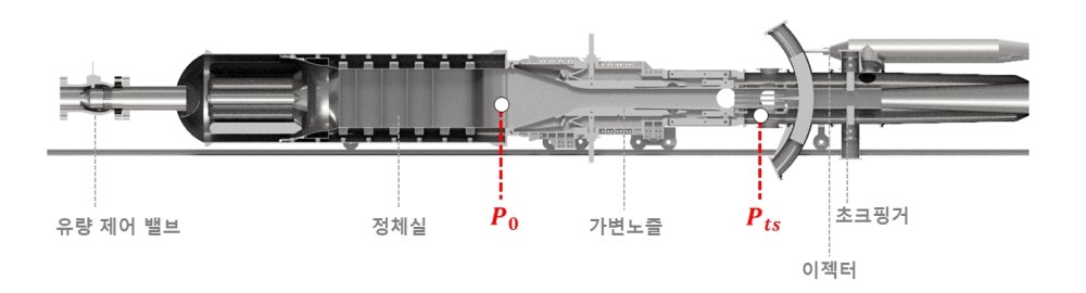
Settling chamber pressure, nozzle area and test section back pressure are controlled at four points.
P0 settling chamber pressure
Flow control valve
- P0 target setting
- P0 pressure feedback
- Valve opening calculation
- Flow control valve output
Variable nozzle
Servo motor control
- Target nozzle area
- Servo position calculation
- Servo motor output
- Encoder feedback
Choke system
Servo motor control
- Test section back pressure
- Servo position calculation
- Servo motor output
- Encoder feedback
Ejector
Flow control valve
- Test section back pressure
- Valve opening setting
- Valve position feedback
Available Tests

How to Use
Usage Procedure
For facility use and test scheduling, please contact the administrative office. Contact details and office hours are on the How to Use page.
Keep Exploring