
Specifications & References
Specifications & References
Specification Comparison
| Item | Trisonic Wind TunnelTrisonic Wind Tunnel | Hypersonic Wind TunnelHypersonic Wind Tunnel | Ballistic RangeBallistic Range |
|---|---|---|---|
| Type | Blowdown | Pressure-vacuum blowdown (electrically heated) | Two-stage light gas gun (piston compression) |
| Test Mach number | M 0.5 – 3+ | M 7.0 | — |
| Launch velocity | — | — | up to 4 km/s |
| Test section | 500 × 500 mm | — | — |
| Nozzle exit diameter | — | Ø 300 mm | — |
| Bore diameter | — | — | Ø 12.7 mm |
| Model diameter | — | — | up to Ø 10 mm |
| Launcher length | — | — | 8 m |
| Test section length | — | — | 4.5 m |
| Window diameter | — | — | Ø 500 mm |
| Test time | ~ 60 s | ~ 30 s | — |
| Angle of attack | −10° ~ +15° | — | — |
| Stagnation pressure | 1 ~ 9.8 atm | 1.0 ~ 2.4 MPa (10 ~ 24 atm) | — |
| Mass flow rate | 60 ~ 200 kg/s | 1 ~ 2.9 kg/s | — |
Site Layout & Utilities
Layout of the trisonic and hypersonic wind tunnel laboratories and the high-pressure air, power, cooling and vacuum utilities
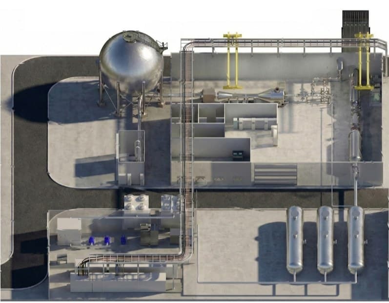
- 01High-pressure air tanksCapacity 200 m³ × 3 = 600 m³ · Max. pressure 40 bar
- 02Cooling water pumpsDrive motor 7.5 HP × 4EA (Total 30 HP) · In-line pump 5 HP × 2EA
- 03Air compressor & dryerMax. pressure 42 bar · Max. capacity 752 L/s
- 04Cooling towerCooling capacity 900 RT
- 05Vacuum tankInner dia. Ø12.5 (1,022 m³)
- 06Vacuum pumpsCapacity 2,700 m³/hr (0.5 torr)
- 07Heat exchangerHeat removal 1,384,000 kcal/hr
- 08Catch-cone variable-length diffuser
- 09Test chamber
- 10Hypersonic nozzle
- 11High-pressure air silencerFlow 2.9 kg/s · Target noise level 65 dB or less
- 12Trisonic silencerFlow velocity 0.6 m/s · Expected pressure drop 1.8 mmAq · Target noise level 75.9 dB(A) at 1 m
- 13Diffuser & ejector
- 14Model support test section
- 15Variable nozzle
- 16Settling chamber
- 17Flow control valve
Trisonic Wind Tunnel Installation Plan
- High-pressure air
- Power
- Hydraulics
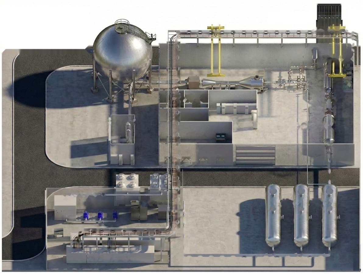 Hypersonic labHydraulic roomOffice / restroomVacuum pump roomTrisonic labControl roomCooling water roomCompressor roomAir storagePower room
- 01Inflow / variable nozzle systemSettling chamber and nozzle in a straight linePrecision leveling against the railsSpace reserved for maintenance
- 02Test section / choke systemConnected on the test section centerlineChoke and diffuser installed without reverse steps
- 03Diffuser & ejector system3 ~ 7° diffusion angle maintainedAnti-vibration pads to reduce vibrationOperating status visible locally
- 04SilencerInstalled at the top of the exhaust stackSound barriers and absorption panels added if needed
Installation Steps
01
Prefabrication & verification
- Main equipment built and pre-assembled in-house
- Delivered in modules after performance and function tests
02
Foundations & early installation
- High-pressure storage tanks and main piping installed first
- Trenches, isolated foundations and alignment rails
03
Delivery & alignment
- Equipment brought in along the rails
- Alignment center secured regardless of upstream or downstream end
04
Utilities & environment
- Compressor, exhaust and noise reduction systems
- Environmental and noise standards met
Infrastructure Plan
- Heavy equipment
- Placed next to the road (reinforced foundations · crane access)
- Storage tanks (19 m)
- Placed on the perimeter (large crane installation + room for expansion)
- High-pressure compressor
- Concrete foundation (space reserved for expansion)
- Vacuum tank
- Location allows expansion
- Remote control room
- 2nd floor of the existing building — remote, unmanned operation
- Maintenance
- Two 15-ton cranes
Comparable Facilities Abroad
Ballistic Ranges
NASA Ames Research Center · USA
Hypervelocity Free Flight Aerodynamic Facility (HFFAF)
- Launch type
- Two-stage light gas gun · Powder
- Bore diameter
- Ø12.7 · Ø25.4 · Ø38.1 mm
- Launch velocity
- 0.2 – 8.5 km/s
- Scale
- ~125 m (23 m long test section)
Texas A&M University · USA
Hypervelocity Impact Laboratory (HVIL) 2SLGG
- Launch type
- Two-stage light gas gun · Powder
- Bore diameter
- Ø12.7 mm
- Launch velocity
- 2 – 8 km/s (two-stage) · 0.1 – 1.5 km/s (single stage)
- Scale
- Pump tube Ø44.5 mm × 2.44 m · Flight tube Ø12.7 mm × 3.66 m · Target tank Ø1.17 m × 1.83 m
JAXA · Japan
Two-Stage Light Gas Gun
- Launch type
- Two-stage light gas gun · Powder
- Bore diameter
- Ø7 mm
- Launch velocity
- max. 7 km/s
- Scale
- ~10 m
Arnold Engineering Development Complex (AEDC) · USA
Hypervelocity Ballistic Range G
- Launch type
- Two-stage light gas gun · Powder
- Bore diameter
- Ø83.8 · Ø101.6 · Ø203.2 mm
- Launch velocity
- max. 7 km/s
- Scale
- Test chamber ~284 m
French-German Research Institute of Saint-Louis (ISL) · France
ISL Hyperballistic Tunnel
- Launch type
- Two-stage light gas gun
- Bore diameter
- Ø10 · Ø20 · Ø30 mm
- Launch velocity
- 2 – 9 km/s
- Scale
- Test chamber ~21 m
Wind Tunnels
Overseas wind tunnel references are being compiled.
They will be posted here once confirmed.
Keep Exploring