
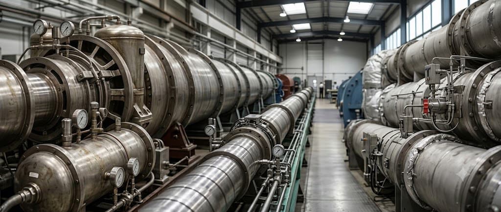
Hypersonic Wind Tunnel
Hypersonic Wind Tunnel
A pressure-vacuum blowdown wind tunnel producing hypersonic flow up to Mach 7.
It supports research on launch vehicle aerodynamics and flight stability during the descent and landing of space probes, with long test times that yield large volumes of aerodynamic data.
Specifications
- Type
- Pressure-vacuum blowdown (electrically heated)
- Test Mach number
- M 7.0
- Nozzle exit diameter
- Ø 300 mm
- Test time
- ~ 30 s
- Stagnation pressure
- 1.0 ~ 2.4 MPa (10 ~ 24 atm)
- Mass flow rate
- 1 ~ 2.9 kg/s
Key Features
01
Hypersonic flight on the ground
- Ground simulation of flight at Mach 5 and above
- Designed to extend the test range to M5 ~ M10
02
Precise aerodynamic measurement
- Six-axis attitude control
- Contoured interchangeable nozzles
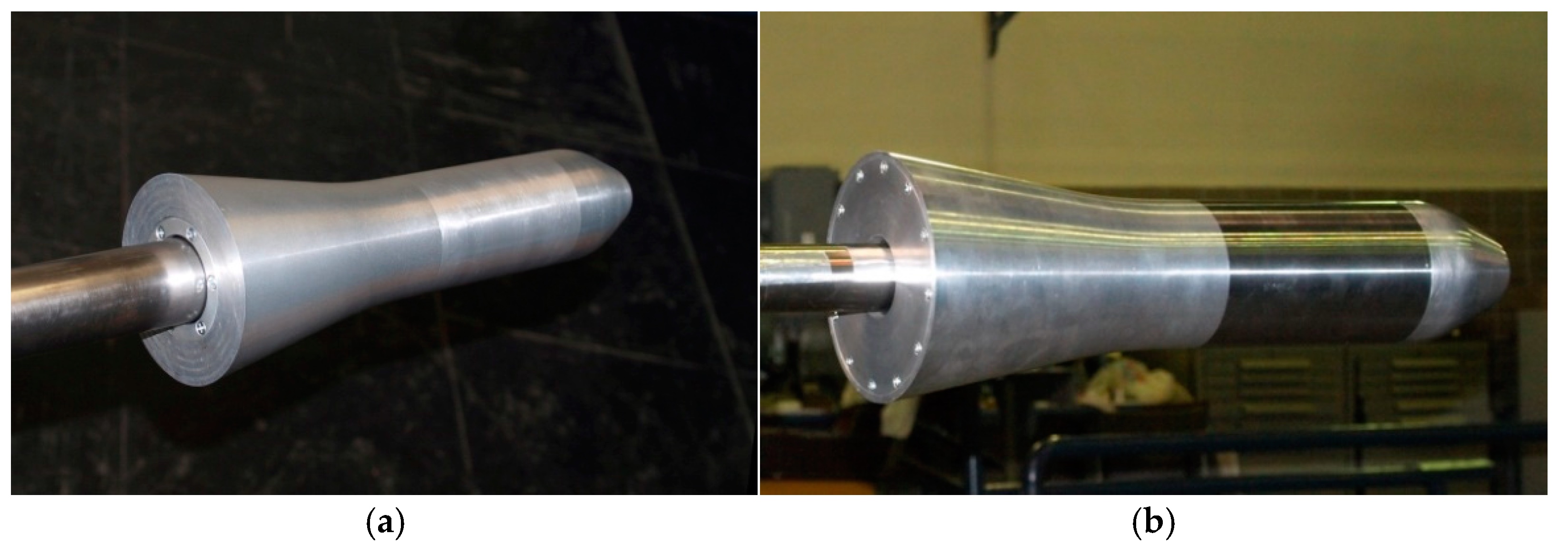
- HB-1 / HB-2 standard model tests
03
Designed for expansion
- Provision for up to 15 kg/s mass flow
- Provision for a Ø 500 mm nozzle exit
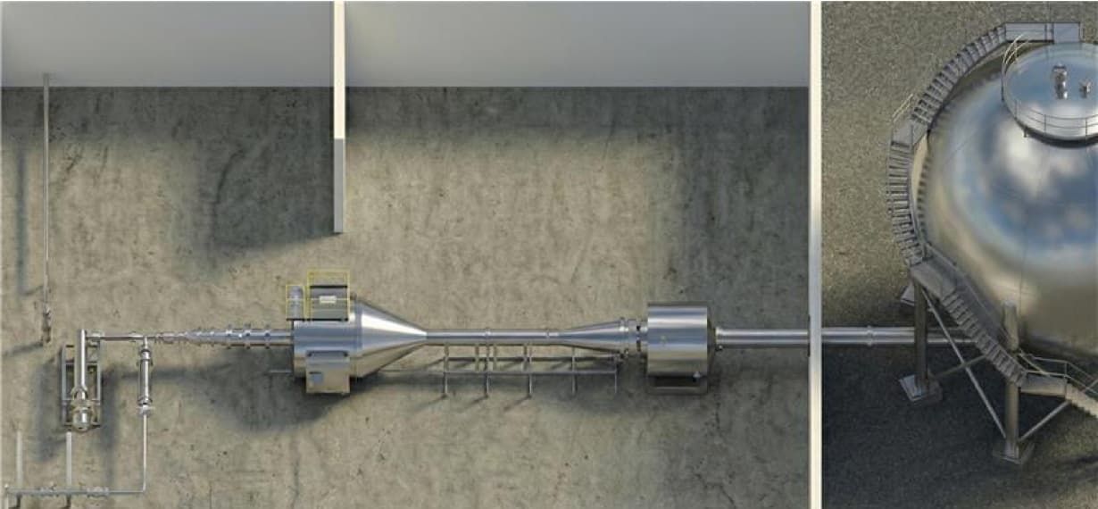
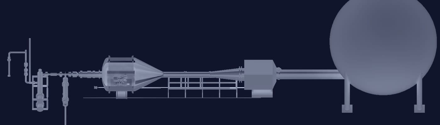
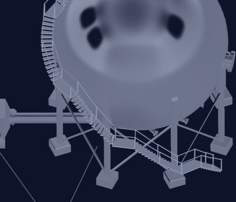
System Layout
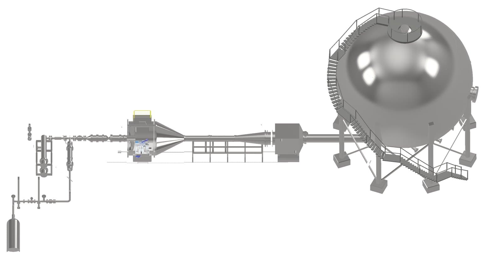
Loading 3D model
Components
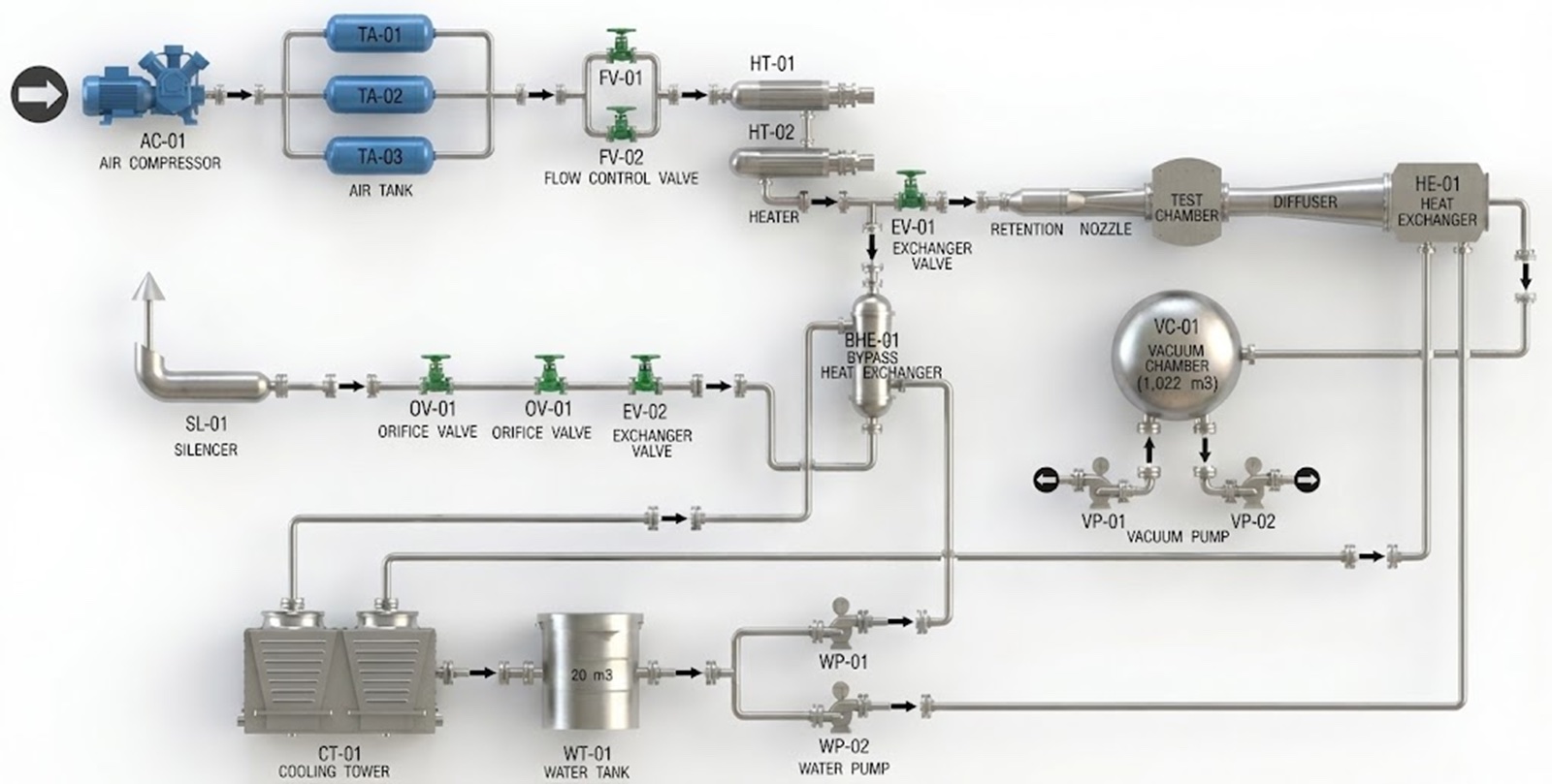
Piping Diagram
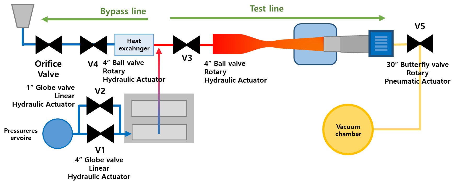
Operating Sequence
Operating Sequence
Air is heated through the bypass line until conditions are met.
The valves then switch to the test line and the flow and test article are measured.
01
Air heating
Bypass discharge, stage 1
- Pressure tracking 10% met · V1 valve open
- Air heater on
- Nozzle-matched orifice valve open
- V4 valve open
02
Air heating
Bypass discharge, stage 2
- Temperature condition met
- Pressure tracking 100% met · V2 valve open
- Temperature met
- Air heating maintained
03
Valve control
Valve switching
- Simultaneous switching — V4 valve close · V3 valve open
- V1 valve fine adjustment
- V2 valve fine adjustment
04
Test measurement
Flow & test article measurement
- P0 · Pts measurement
- Test model injection
- Scanivalve measurement
- Balance measurement
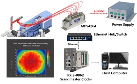
Available Tests
Achieving Test Conditions
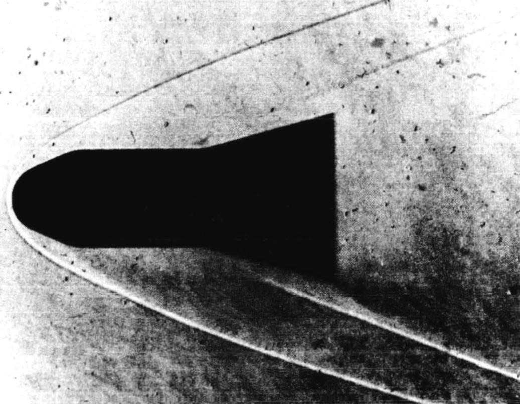
Test conditions are set from measured stagnation pressure and temperature, and flow quality is confirmed with HB-1 / HB-2 standard model tests and auxiliary verification.
- Operation
- Blowdown
- Mach range
- M 7.0 and above
- Nozzle
- Contoured interchangeable nozzle
- Condition measurement
- Based on stagnation pressure · stagnation temperature
- Standard model tests
- HB-1 / HB-2
- Auxiliary verification
- Multi-point pressure rake · schlieren, etc.

How to Use
Usage Procedure
For facility use and test scheduling, please contact the administrative office. Contact details and office hours are on the How to Use page.
Keep Exploring